Google Analytics tags

Thursday, April 29, 2021

Avoiding a dead battery by adding a Headlight / Turn Signal left on while parking Warning Buzzer


In a Porsche 993, the "chime relay" provides the car's warning chimes, which are the audible sounds that alert the driver about various situations such as leaving the headlights on among other functions. If one replaces it with the IMMO BLOCK the headlight-left-on chime function is lost. This aftermarket update restores the warning chime for the headlights.

Velleman product is no longer available but there are several functionally identical kits that use the same wiring connection points that can be found by searching the internet  for "Car Headlights Warning Buzzer:

If the Velleman proves to be unavailable here is an alternative for the same purpose:
Scott Drake C6AZ-14931-AR - Scott Drake Warning Buzzers

Like the Velleman kit, any other kit will require only three wires to hook up. One is to constant on power, one is to the ignition switch, and one is to body ground, as discussed below.

 If you want to add a headlight/turn signal left on a warning buzzer, well more like a bird chirp, to your car, it is quite easy. There are several kits out there to do this. I used the Velleman K3505 kit:

It is a great companion to the IMMO BLOCK and is compatible with it.


Disclaimer: The content of this page, relates specifically to the Porsche 993 (911 1995 to1998) The author here is not a professional automotive technician and some of the procedures described on this page may not be the best to use in all situations. Though the author strives to provide completely accurate and appropriate information and attempts to keep it up to date, in some cases, some of the information you find on this page may be outdated or in error therefore, please feel free to use the information on this page at your own risk.


Wire connections:

  • One wire from the connection block on the device marked "GND" goes to the car body (-)
  • A second wire is attached to the connection block marked "C" and to continuously positive (+) circuit under the dash such as the one to the ignition switch or the radio or possibly pin 'X"  or the violet wire on the headlight switch, although I have not tested this so a little experimentation may be required. If one has a concern about a parasitic load when the car is parked one could connect the wire from block "C" on the device to the circuit that supplies the dome lights. In this way when the dome lights go out the device is rendered unpowered and inactive. I have not tested this but it should work.
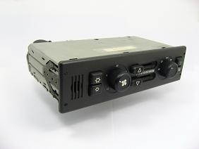
  • A third wire is attached to the connection block marked "L" to the headlight switch headlights active pin or the accessory pin depending on the function desired. For example, if the warning is just for the headlights remaining on consider pin 30h or pin 30 the red wire or one of the other pins if you want to be warned you left the turn signal on the opposite side of the car when parked. A little experimentation may be in order to get the function you are looking for. see the diagram above from the 993 wiring documents for insights into how the headlight switch works.  
  • Finally, a short length of wire is to be used as a connection strap between the two J2 (jumper #2) connections on the device.


This K3505 headlight indicator module may be set for one or two functions. To indicate that the headlights (or the sidelights) should be switched off after switching off the ignition contact (battery protection). Or to indicate that the headlights should be on once ignition contact is switched on (obligatory in some countries).


Module K3505 Specifications
Continuously repeated alarm tone for lights ON (may be disabled)
Repeated alarm tone for lights OUT
Only 3 wires are required for hook-up
Supply voltage: 12V battery
PCB dimensions: 48 x 57mm / 1.9 x 2.2"
Here is a page on adding automatic door locks as well. This modification is also IMMO BLOCK compatible

In my car, I put both the headlight warning module and the automatic door lock module in a plastic soap box under the dash where they have been functioning perfectly for years. I know someday in the distant future some future owner of my car, probably my son, will find the soapbox and wonder what the hell the PO did.


If you found this page informative return to the main page and bookmark it for future 993 related servicing, repair, and upgrading guidance & information. If it saved you some time aggravation or even a little coin consider a donation through the button on the top left margin of this page.


Thursday, April 22, 2021

Servicing Seats, Doors & the Sunroof

The 993 shop manual is really just an appendment to earlier 911 shop manuals. Looking back here are select sections found only in earlier shop manuals that for the most part apply to the 993:

Sunroof Servicing -- This is a rather complete servicing document.

Door Servicing -- This is a section from the '80s Carrera that is similar in methods of servicing

Seat Servicing  -- This is a limited section on seats describing their function from an earlier 911

If you found this page informative return to the main page and bookmark it for future 993 related servicing, repair, and upgrading guidance & information.

Saturday, April 17, 2021

Getting the leather upholstery edge to stay in place on the Hard-Back Factory 993 Sport Seats


As our cars have aged the leather upholstery incrementally shrinks and becomes stiff. Also, the seatback leather has a rubber gripper-edging to hold the leather in place that becomes stiff and brittle losing its ability to grip. These items together seem to cause the seat edge leather to pull free from the seat's plastic hardback.

The immediate and simple fix is to:

--Soak the front and the back of the leather with Lexol leather conditioner to soften the leather and;
--Then buy some extra of the original metal hold-back clips part number 999.507.526.01 and add them to what are already there;

This will reduce the problem but did not eliminate it completely.

Alternatively, 
When I replaced my seat covers the new covers used a round cross-section rubber bead similar to the ones used on window screens that is force-fit into the cuff along the entire periphery of the seatback pinching the leather solidly in place. 
This type of attachment has been on my car for six years and
the leather has not slipped out. 

For this reason, getting some home window screen beading material at a DIY store and working it in up against the existing dried-out rubber gripper-edging will probably do the trick. I used a non-marring plastic scraper-chisel from Harbor freight or Amazon to install the beading on my replacement seat covers.


If you found this page informative return to the main page and bookmark it for future 993 related servicing, repair, and upgrading guidance & information. If it saved you some aggravation, time or even some coin consider a donation through the button on the top left margin of this page. 

Monday, March 8, 2021

Fan resistor update for Oil Cooler and AC Condenser Fans

The 993 has a known issue with defective low-speed resistors that power the oil cooler and AC condenser fans. They fail from moisture exposure and heat cycling. 

Replacing them as originally installed involves disturbing AC and Oil cooler components and their hoses on a 25+ -year-old-car that maybe shouldn't be messed with and will take a few hours to accomplish. 

This DIY  is a minimally invasive how-to to make resistor assemblies from resistors available from eBay or really any electronic supply store and relocate the resistors to a more accessible location behind the headlamp pods. If the existing resistors are abandoned in place and pigtail wires are obtained from another source this DIY involves no body or component disassembly at all!

Please read this document completely from beginning to end before attempting this project. The author of this page is not a professional automotive technician or engineer therefore, please feel free to consider this project at your own risk.

The items needed:

Quantity 4,  100W 0.8 Ohm aluminum housed resistors, two used in pairs to replace each single fan resistor in each assembly;

Quantity 2,  Discarded OE fan resistor wiring pigtails with plugs on the end. These can be the ones clipped from your original resistors abandoned in place or possibly request a couple failed & discarded resistors from someone on a 993 technical forum or secure some through a dismantler. If you clip the pigtails from your old resistors the one on the left side is easy to get to through the headlight pod opening. The one on the right side will require removing the wheel well liner to obtain.

The below wire, sheath, and heat shrink tube insulation items are only needed if the salvaged pigtail wires recovered from the old resistors are too short for the pigtail plugs to reach the wiring harness sockets. Doing some trial layouts will help in determining if extending the pigtails is necessary.

Quantity 4, 1-foot sections of  GXL grade heat-resistant stranded primary wire in 12 or 14 gauge and 

Quantity 2,  1-1/2 foot sections of heat-resistant insulating sheath to cover them. 

Quantity 2, 2-inch sections heat shrink tube insulation suitable for insulating 12 to 14 gauge primary wire.

The above three items are easily purchased in small quantities on eBay.

An alternative wire and sheath source to lengthen the plug wires is to secure quantity 2 discarded Bosch oxygen sensors. Most any shop that service European cars have a couple of these in their trash bin. Also if you were considering refreshing your car's oxygen sensors save the old ones for this project. The oxygen sensor pigtail includes two white heater wires and a wire sheath that are the proper gauge and are made of heat and abrasion-resistant material and are ideal doner wires and sheathing to lengthen the resistors' pigtail wires. 


General fabrication supplies needed include: 

  • Solder & a 75 Watt soldering gun;
  • Aluminum roof flashing sheet, something purchased at a home improvement store; 
  • An inexpensive pop-rivet gun and; 
  • Small diameter aluminum pop rivets;
  • A role of 3M type 33 or 88 Electrical tape;
  • A roll of aluminum (heat resistant) duct tape.

Making the resistor assemblies:

  • Cut off and use the wire pigtails and wire sheath from the OE resistor assemblies.
  • Extend the pigtails if needed. Abandon the original pigtail sheath and splice the added wire using staggered solder joints along the original pigtail wires so the spices don't overlap each other eliminating the possibility of them shorting together.  Insulate the individual wire splices with some heat shrink tube and snake the wires through the replacement outer sheath before soldering them to the resistors. This method avoids using electrical tape not designed for potentially high temperatures.
  • Once the pigtail is soldered to the two resistors in parallel paint the resistor's bare solder connections with nail polish to minimize corrosion over time as shown below.


Remove the headlight pods and pull the wiring harness sockets used by the old resistors out where you can plug the new resistor pigtail into the harness. They are on the inner frunk sidewall on each side of the car behind the headlight pod. The harness socket is readily visible on the left-hand side of the car. On the right-hand side, the harness' plug is a little too far forward to see but if one pulls on the wire leading forward it will unplug, releasing it where it can be pulled back and accessed through the headlight opening without further disassembly of the body.

  • Trim the aluminum sheet and fold it in an "L" so it forms an angle bracket with a length about an inch longer than the length of the resistors and their wire attachment points. 
  • One side of the L will form the base to attach the resistors and should be about 2" wide
  • The other side forming a vertical wall about 2-1/2" inches tall.
  • The vertical wall is then cut in a curve matching the profile of the outer body curve above its planned placement. 
  • This curved edge will also act as a stop when sliding the bracket forward to its final installed position. By acting as a physical stop from sliding forward it will protect the forward-facing electrical connection on the resistors from touching the body.
  • This vertical wall will tuck behind the rolled edge of the headlight opening in the body above it.
  • Trial tuck the trimmed and folded sheet above the existing headlight bracket on the frunk side of the headlight opening as shown below.

  • Attach the resistors to the aluminum sheet using  4 pop-rivets, 2 per resistor, so the sheet metal bracket extends past the exposed resistor end electrical connections. 
  • You may need to slightly ream out the existing mounting holes on the resistors with a drill bit so the pop-rivets can pass through them. 
  • Apply the pop rivets from the sheet metal side (bottom) of the resistor mounting attachment points. 
  • The resistors should be attached to the bracket in such a position so it precludes their end connections from physically being able to touch any part of the body when the complete assembly, resistors & sheet metal is tucked as far forward as it can into its final position. Cover the sharp edges of the sheet metal with electrical tape where it will touch the body of the car to protect the body paint from being scratched.

  • Shown below is the assembly partially placed in position. When fully placed the vertical wall formed by one side of the sheet metal folded "L" should be tucked behind the body opening edge lip above it. By doing this it will completely clear the headlight pod when the pod is slid back in. Once the assembly is in position plug the pigtail into the wiring harness and tie the wires neatly as needed using tie-wraps.

  • Use a small patch of heat-resistant aluminum duct tape, as shown below,  to anchor the assembly in its final position so it does not move over time.
  • Reinstalling the headlight pods can be greatly facilitated by spraying their mounting tracks with a little Teflon or Silicone spray lube and rubbing a little of the lube with your finger on the pod's electrical connection socket seal 

Testing the Resistors:
  • Once installed the resistors can be tested by pulling the two relays that control each fan in the fuse box and jumping each relays' two low-speed spade sockets. 
    Relay Test Jumper In Position
    The spade sockets to jumper are labeled on both relays, they are spades 30C & 87C and are located directly across from each other in each relay socket. 
  • The jumper can be made from a piece of 14 to 12 Gauge solid core copper primary wire, easily pulled from a roll of solid core Romex primary wire.  Strip the ends of a small section of wire and hammer the ends flat to form small spades that will fit into the relay's sockets. There is no need to have the ignition on in the car to do the test. Also if while you have the relay out you would like to test the fan motor through the high-speed setting,  jumper spade socket 30 to spade socket 87.


Relay Test Jumper wire with
the ends hammered flat

  • The resistors do heat up a bit and if one would like to test how much just run the fans with the jumper for three to five minutes and they will reach their terminal temperature somewhere a bit north of 130 degrees although I did not take a measurement. It turns out the pigtail wire connections to the resistors and the pigtail wires themselves tend to stay cool when I ran this test, go figure?
A Safety Enhancement: A safety enhancement to the above assembly design would be to add an in-line fusible link, a thermal fuse, or a thermal cut-off switch mounted to the bracket with adequate amp capacity for the application. The added fuse/switch would only come into play if the fan's electrical motor connection shorted to ground causing the resistors to experience excessive current and generating high heat levels before their failure. 

6/22/2023 -- Having the above resistors installed in my '96 Carrera for quite a few years now, they have proven to be durable and trouble-free.

    If you found this page informative return to the main page and bookmark it for future 993-related servicing, repair, and upgrading guidance & information. If it saved you aggravation, time, effort or some coin consider a donation through the button on the top left margin of this page


    Sunday, March 7, 2021

    Does the cabin air recirculation button on the Climate Control Unit seem to not do anything, a known problem with a quick fix.


    The button on the Climate Control Unit (CCU) with the little circular icon is designed to turn on cabin air recirculation. 


    It controls a solenoid air valve behind the dash that then controls a vacuum actuator behind the CCU in the dash. The actuator's pull rod is attached to the vent mechanism by a black plastic push rivet. The actuator's arm comes loose from the rivet and the mechanism is no longer actuated, see the below picture. This is a very common failure and when it detaches the air recirculation button on the Climate Control Unit no longer functions. 


    Photo credit user "Alpha 40" on Rennlist


    The fix is to remove the black plastic push rivet if it hasn't already gone missing and loop a tie-wrap through the hole the rivet was in and then through the metal arm's hole and close the tie-wrap. This is the repair I did and it has lasted for years. Some go to the extra effort if using a machine screw and two nuts as jamb-nuts to work as a pin in the same way.

    It is so common a problem I suggest everyone test their recirculating air button. To test it run the car a little to build vacuum reserve, park, and turn the engine and cabin blower off but leave the ignition on. Press the recirculation button on the CCU and release it. One should hear a "thwack" sound as the actuator moves the air control valve. No "thwack" and the arm has come loose.

    The first section on this page discusses how to remove the Climate Control Unit (CCU) to gain access to the recirculation acuator for servicing.

    Earlier cars didn't have the actuator mechanism and therefore no "thwack" so if you have an early production 1995 or an earlier model year car the mechanism may not be present or present but not attached. If you care to check just pull the CCU and look behind it while pressing the CCU's recirculation button.

    •  If you see the actuator's arm move and not open the vent it has become detached; 
    • If your car is an early production 1995 model or earlier and the actuator's arm doesn't move and the actuator or some of the arms are detached or simply not present the mechanism may just be something that was orphaned at the factory during a design transition/part supersession and no repair is required.

    Here is a little video supplied from Rennlist by user "bobpyb" that shows the actuator mechanism in action:  https://youtu.be/-jusuIO3wuY


    Also if any of the pushbuttons are broken on your CCU they can be replaced Here:
    Replacement CCU Push Button Switches


    Here are other pages related to the HVAC system:


    If you found this page informative return to the main page and bookmark it for future 993 related servicing, repair, and upgrading guidance & information.


    #CCU #climate #recirculate #cabin #HVAC #door #buton #thwak #sound #vacuum #actutor #solonoid

    Saturday, March 6, 2021

    Fun Facts Concerning the HVAC system in a 993


    I was recently reading a posting by Tore from Bergvillfx.com concerning the mercurial workings of the heater blower fan in the engine compartment and found it very interesting:

    "The rear fan(s) has two purposes. 

    • One is to help blowing air through the heat exchangers onward to the front fans to fan improve the heating of the cabin. 
    • The second function of the rear fan is to do additional cooling of the heat exchangers/engine when in normal operation.

    When blowing heated air to the cabinthe fan runs at two speeds. 
    • Low speed if the fan speed knob on the CCU is below 2. 
    • Fan settings above 2 will set the rear fan speed to high. 
    The operation of the fan is also dependent on the temperature setting, i.e.:
    • if [ the cabin] temp is set to minimum, the rear fan will not start since no heated air is needed to the cabin. 
    • However, on minimum [cabin] temp setting, the fan could automatically be started by the [engine] cooling function.

    In [engine] cooling mode, the rear fan runs at two speeds depending on the reading from the engine compartment air duct temp sensor. Heated air is dumped out through the two rubber spring-loaded dump valves under the engine. On low speed, the airflow may seem to come out of only one of the dump valves."

    Also, Tore's website https://www.bergvillfx.com contains a vast treasure trove of information on how the Climate Control Unit (CCU) in the dash controls all the other aspects of the Heating, Ventilating & Air Conditioning system (HVAC). 

    Also, there are two types of actuators used in the HVAC system:
    If you found this page informative return to the main page and bookmark it for future 993 related servicing, repair, and upgrading guidance & information.

    Monday, February 1, 2021

    Failed Engine Mounts & Engine Carrier


    Engine Carrier

    Symptoms of a failed engine mount or bent engine carrier:

    • A sudden change or degrading of shifting feel
    • One or both of the exhaust tips appear to be sitting low in the rear bumper cutouts

    Engine Mount

    Failed Engine mounts:

    There are two engine mounts in the 993/964 that can be seen

    in the rearmost left and right sections of the engine compartment. The engine hangs below them held in place by the mount's threaded rod and nut that holds the engine up by the engine carrier. The original ones are fluid-filled with the intent to isolate a good bit of engine vibration from the body of the car and so reduce noise and body boom. When they fail the fluid leaks out and the engine drops slightly from its correct position. If original to the car, one can look and see if they see remnants of the fluid around the mounts suggesting one or both are leaking and need to be replaced.

    Installed mount
    attached to the carrier. 

    If one suspects they have failed mounts they can be tested by sliding a floor jack under the center of the engine, just forward of the oil drain plug to the reinforced section of the center spine of the engine case, and using a hockey puck as a cushion lift the engine an inch or two and no more. If more than a tiny amount of vertical travel of the tailpipe tips is observed one or both mounts have failed. In either case, the mounts

    should be replaced in pairs as both are probably of similar age and use.

    The engine mounts can be replaced with the original or

    Non-fluid filled
    Aftermarket Mounts
    Aftermarket fluid-filled designs or several offerings of aftermarket mounts that do not feature fluid-filled vibration isolation. Non-fluid-filled mounts cater to those who like the idea of a stiffer mount or wish to save a little money as the fluid-filled OE mounts are expensive. Be aware these stiffer mounts may increase vibration and noises heard in the cabin that may be objectionable to some. 

    If one notices one or both tailpipe tips are higher than normal the cause may be due to the tips grounding on a parking block, speed bump, or a steep driveway apron. In this case, the clamps that hold the tips can be easily loosened using a pair of box wrenches, and the tip(s) repositioned in their proper orientation.

    Failed engine carrier:

    If the motor mounts prove to be good from the above test and

    OE carrier with right-hand side bent upward
    one of the tailpipe tips seems to hang lower than normal the root cause may be a bent engine carrier. The engine carrier is the steel cross member the engine mounts are attached to that holds the rear of the engine. It can be observed to see if one side of the carrier is bent upward. It can be repaired and reinforced by a welding fabricator or it can be replaced with an original OE part or a more durable aftermarket replacement.


    If you found this page informative return to the main page and bookmark it for future 993 related servicing, repair, and upgrading guidance & information. If it saved you some aggravation, time or even some coin consider a donation through the button on the top left margin of this page.

    motor mounts

    #motor mount

    motor carrier

    #motor carrier

    Saturday, January 30, 2021

    993 Rotor Wear, Evaluation & Replacement

    Please read this document from beginning to end before attempting the below procedure as there are dependent steps and notes that should be in mind before beginning.

    When to replace rotors:

    Rotors have a long service life on a 993 lasting between 60 and 80 thousand miles in most cases. They should be replaced when they approach their wear limit (minimum thickness) or 30mm in the front and 22mm in the rear. 

    When one approaches these minimums the brakes can exhibit greater brake noise. With use, 993 rotors develop a ridge on the outermost circumference of the rotor faces. This is where the pads do not come in contact all the way to the outer edge of the rotor. If one can feel a substantial ridge develop here with one's finger, brake performance, brake feel or noise is present it indicates the rotors should be checked for wear. The difference between a new rotor and one worn to replacement thickness is only 2mm. 

    Resurfacing rotors have fallen out of favor as in the process the service life is literally cut from the rotor face and new rotors from the original suppliers to Porsche have become somewhat inexpensive as replacements if purchased outside the dealer network. Seeing that replacing them is one of the most basic and simple service items done along with pad replacement it is well suited to a Do-It-Yourself approach to replacing them. For most folks, rotors are a once in life of vehicle replacement item.

    The below page is from the 993 1994/1995 Technical Specification Booklet. Specifications subject to change:


    Disclaimer: 

    The content of this page, relates specifically to the Porsche 993 (911 1994 to1998) The authors here are not professional automotive technicians. Some of the procedures described on this page may differ from official factory recommendations and may not be the best to use in all situations.  For these reasons use the information contained on this page at your own risk. Many times a lot can be learned by simply watching qualified professionals work on your 993.

    Special tools needed:

    • A breaker bar and socket for removing the caliper mounting capscrews;
    • A manual impact screwdriver (inexpensive at Harbor Freight);
    • A 5" to 8" jaw size C-Clamp;
    • A click-style torque wrench. Be aware that torque wrenches when set near the ends of their torque value range are usually not very accurate so size the torque wrench you use so the required torque value falls somewhere in the middle third of its adjustable range if at all possible.

    Ordering parts and supplies needed:

    • Order the 4 rotors;
    • Pre-order 4 replacement cap screws for all years of 993 and washers as well for 1994 for mounting the front calipers, see part numbers below. Porsche recommends replacing these whenever a front caliper is removed. It probably has to do with corrosion or debris scoring the fillet under the head during removal of the fastener significantly weakening it. 
    • If you live in an area where you expect to see corrosion on the mounting capscrews it is probably a good idea to order and replace the 4 used to mount the rear calipers as well.
    • A brush-bottle of anti-seize
    • Brake Fluid to top off the reservoir.
    • A can of spray electronic cleaner.
    • 2 Cans spray brake cleaner.
    • Some dielectric grease.

    Front Caliper mounting Capscrews and Washer:


    The remarks column above refers to Model Year.

    The model column refers to as below:

    M493 = Narrow bodywork car; 

    M339 = 4 wheel drive; 

    M491 =  Carrera 4S.


    Rear Caliper Mounting Capscrews:


    It is unclear to me what the "A" prefix in a part number or why two lengths of capscrews are specified for the rear calipers in the catalog. They may be interchangeable or two different lengths were used based on VIN. This is a good question for the dealer when ordering the capscrews.

    Procedure steps:

    • Break free and gently resnug the wheel nuts on the wheel-end you will be lifting off the ground to replace a rotor. Each wheel-end can be worked on individually lifting and lowering each wheel-ends as you work your way around the car replacing each rotor;
    • Lift the wheelend off the ground. This page discusses safely putting one's car on a jack stand(s)
    • Remove the wheel nuts and wheel-with-tire. Be sure to put the wheel-with-tire on the ground face-up where you will not scratch the wheel;
    • Unplug the wheel brake-pad  wear sensor wire pigtail if a sensor is present;
    • Draw down the brake reservoir with a turkey baster or a syringe before working on the rotors. After installing each new rotor I pump the brake peddle a little pushing the caliper pistons against the pads and new rotor. In this way it avoids the cumulative effect of all the wheel ends having all their piston cups pushed in causing a good volume of brake fluid to back up into the reservoir potentially overflowing it and making a mess.
    • I compress the caliper piston cups using a "C" clamp with the original pads and rotor still in place. Placing the clamp along the top edge of the caliper casting and the pad backing plate. If you have a concern about scratching the paint on the caliper face one can use a little patch of rubber to protect it from the "C" clamp's jaw. This is done so the caliper with pads are backed off to clear the outer edge of the old rotor when sliding the caliper off and allows added clearance when mounting the caliper over the new thicker rotor. 
    • Unbolt the caliper from the wheel carrier. This will take the use of a more robust 1/2 drive socket and breaker bar; 
    • Slide the caliper off the rotor. 
    • Use some coathanger wire to hang the caliper out of the way without excessively twisting the brake hose;
    • Remove the small M6x12 Countersunk Head 900.269.047.09 hold-down screws on the face of the rotor's hat attaching it to the wheel hub. These screws are usually seized if not previously removed.  They are easily removed without damaging it by using a manual impact screwdriver & hammer to pop them loose;
    • Slide the rotor off  of the wheel hub;
    • I use some brush-bottle anti-seize and very lightly coat the hub face where it comes in contact with the rotor. Use it sparingly as otherwise, it may migrate to the face of the rotor when in use;
    • If the new rotor is covered with a heavy anti-corrosion coating hose off the front and back pad contact faces with some spray brake cleaner. This can be done before or after they are mounted in position. If the faces seem bare and dry this step can be omitted;
    • Slide the replacement rotor on the hub so the hold-down screw hole(s) lines up with its matching threaded hole(s) in the hub;
    • Reinstall the hold-down screw(s) using a little anti-seize on its threads and the underside of its head;
    • Reinstall the calipers, and torque the mounting capscrews to 85NM. Use new caliper mounting cap screws on the front calipers.
    • As each wheel end is completed press the bake peddle as discussed earlier in this procedure. 
    • If your caliper capscrews are used in conjunction with washers be sure to use fresh capscrews AND washers with the washer's smooth side facing the underside of the capscrew's head. Check with the dealer as the later model years use a cap screw with a built-in washer face and may be a suitable supersession for the screw & separate washer. Using the washers with the roughly stamped side facing the cap screw head can damage the fillet radius under the head significantly weakening the fastener. 
    • If corrosion is present on the rear caliper mounting capscrews, I would consider replacing them as well. 
    Some use a small amount of anti-seize on the caliper mounting bolts to thwart future corrosion. Be aware this lowers the applied mounting torque required, lower than the factory specification, for these fasteners to achieve the designed clamp load. If the torque is not properly adjusted it may compromise the fastener connection creating an unsafe condition.
    • Plug the brake pad wear sensor wire pigtail back in. 
    • Remount the wheel-with-tire and lightly snug the wheel nuts;
      • I use a small amount of anti-seize applied to the rear of the wheel at its contact points to the rotor hat;
    • Remove the jack stand and lower the tire onto the ground;
    • Retorque the wheel nuts in a star sequence to the recommended torque (130Nm) and check the value by reapplying the torque in a star sequence;
    • Before driving away pump your brakes several times to use up the space between the new rotors and the pads to avoid an initial peddle sinking to the floor braking experience. and check the level in your braking system master cylinder reservoir and top off the brake fluid as needed.
    • Be aware it takes a while for the pad/rotor interface to fully mesh so don't drive aggressively until you have a few miles on your new rotors and the pads have fully bedded into them.
    • If you applied a bit too much anti-seize to the wheel mating points it may become visible on the wheel after a few miles. It simply can be wiped off;
    If you found this page informative return to the main page and bookmark it for future 993-related servicing, repair, and upgrading guidance & information. If it saved you some coin consider a donation through the button on the top left margin of this page.


    Wednesday, January 13, 2021

    Cracked ceramic valve liners, Porsche 993

     P

    Photo Credit Peter Mzr from Facebook


    1. " I double checked with Bruce Anderson on this, and he points out that 911's worked fine forever without ceramic liners. I believe it was an optimization for emissions as much as anything else, to get more heat into the cats more quickly. My understanding is that when machine shops redo late model heads if there is a problem with the ceramic liners they just get rid of the material. This is also done by necessity whenever the ports are enlarged for performance applications. I don't know if anyone has tried to have them recoated. Most everyone seems comfortable not worrying about it though. But if you think the cracking is enough to where pieces could flake off, and clog up the cat, then have the shop work the ports now to shake free anything that is going to fall off eventually. You might want to just have them take the stuff out and polish the ports. If you really want to replace the heads, I would shop around some of the Porsche salvage yards that advertise in Panorama magazine. There are good used heads out there at a fraction of the new prices, which are astronomical.

      Joel Reiser"

    Tuesday, January 5, 2021

    Automotive Glass Manufacturers In Germany by DOT Location Number

    DOT 25
    Manufacturing Location

    The US Department of Transportation (DOT) requires all the glass to be labeled with a DOT code number that signifies at what factory location a glass component was manufactured.  Here are the locations in Germany. It is interesting to note that for a 993 all the windshields seem to have come out of the same two locations** regardless as to if it is Porsche branded with the triangle-P logo above or is sold under the manufacturer or some other brand.

    Automotive Glass Manufacturing Locations in Germany:

    DOT25 FLACHGLAS AUTOMOTIVE GmbH WITTEN, GERMANY**

    DOT27 SEKURIT SAINT-GOBAIN DEUTSCHLAND GMBH GERMANY**

    DOT111 GEBR.HAPPICH GMBH WUPPERTAL, GERMANY

    DOT112 ROEHM GMBH CHEMISCHE FABRIK DARMSTADT, GERMANY

    DOT201 GLAVERTA AACHEN, GERMANY

    DOT231 FARBENFABRIKEN BAYER GMBH LEVERKUSEN, GERMANY

    DOT256 BMW MOTORRAD GMBH MUENCHEN, GERMANY

    DOT278 BRAAS AND CO. GMBH MANNHEIM-NECKARU, GERMANY

    DOT349 BISCHOFF GLASTECHNIK BRETTEN, GERMANY

    DOT406 INTERPANE SICHERHEITSGLAS GMBH AND CO. HILDESHEIM, GERMANY

    DOT448 GLAS KERAMIK BERLIN, GERMANY

    DOT461 PV ELECTRIC GMBH MUNICH, GERMANY

    DOT484 AKENER FAHRZEUGGLAS GMBH SACHSEN-ANHALT, GERMANY

    DOT492 PHOTOTRONICS SOLARTECHNIK GMBH PUTZBRUNN, GERMANY

    DOT500 94BA AUTO GLASS GMBH & CO. KG BERLIN, GERMANY

    DOT662 HT TROPLAST AG NORDRHEIN-WESTFALEN, GERMANY

    DOT665 KUNKELMANN KUNSTOFFVERARBEITUNGS GMBH 64732 BAD KONIG, GERMANY

    DOT666 JOSEF WEISS PLASTIC Gmbh MUNCHEN, GERMANY

    DOT671 FLACHGLAS AG NORDRHEIN-WESTFALEN, GERMANY

    DOT672 FLACHGLAS AG WERNBERG, BAYERN, GERMANY

    DOT679 SEKURIT SAINT-GOBAIN INTERNATIONAL D-52014 AACHEN, GERMANY

    DOT709 FKT GMBH PFORRING, BAVARIA GERMANY

    DOT713 FLACHGLAS WERNBERG GMBH WERNBERG-KOBLITZ BAYERN/OBERPFALZ GERMANY

    DOT738 KESSEL GMBH LENTING GERMANY

    DOT744 FREEGLASS GMBH & CO. KG SCHWAIKHEIM GERMANY

    DOT780 PLASTIC-DESIGN GMBH BAD SALZUFLFEN NORDRHEIN WESTFALEN(NRW) GERMANY

    DOT796 KRD SICHERHEITSTECHNIK GMBH GEESTHACHT GERMANY

    DOT802 POLARTHERM-FLACHGLAS GMBH GROSSENHAIN SAXONIA GERMANY


    Saturday, January 2, 2021

    Porsche TSB 9401 2007


    The Climate Control Unit (CCU) functions


    The Climate Control Unit (CCU) in the Porsche  993 has the following functions:


    1. Monitor the air temperature in the cabin by blowing air over a sensor in the CCU front panel (CCU fan)
    2. Monitor the CCU fan operation
    3. Monitor the ambient (outside) air temperature
    4. Monitor the oil temperature
    5. Monitor any freezing of the A/C evaporator
    6. Monitor both front fans and rear fan operation (fault detection)
    7. Monitor the air temperature in the two front and mixer chambers (vent air temperature)
    8. Monitor the engine temperature to be able to run the aux fan in cooling mode at ignition off if needed
    9. Control the A/C condenser fan low-speed setting. (high speed controlled by pressure switch)
    10. Control the oil cooler fan in the right front fender (low and high speed)
    11. Control the front interior fan speed (two fans, 4 steps using PWM)
    12. Control the engine compartment (rear) cooling/hot air blower fan (low and high speed)
    13. Control the amount of fresh air from the front air intake (servo motor)
    14. Control the amount of heated air from the engine heat exchangers (two mixer servo motors, one for each side of the dashboard)
    15. Control the amount of air to the defroster or center vents (servo motor)
    16. Control the amount of air to the footwell vents (servo motor)
    17. Control the recirculation vacuum actuator behind the CCU on late 1995 and forward cars.
    18. Control the A/C compressor clutch mechanism
    19. Monitor the gear shift, if reverse gear is selected, both mixer valves close to avoid exhaust fumes in the cabin
    20. Activate the DME Coasting Shutoff function in the engine control unit
    21. Log any faults detected in the systems and present them through the OBD interface