Google Analytics tags

Thursday, July 30, 2020

Rebuilding your shift linkage? Here is the soft parts list to consider replacing including hard to identify part numbers.


Over time the 993 shift linkage is subject to developing play with use. Most of the play is from assorted plastic bushings or the plastic ball cup socket at the bottom end of the shift lever all just a few dollars in parts. One source of poor shifter feel may be the rubber coupler at the end of the shift rod further back where the mechanism attaches to the transmission's internal shift rod.

Here is a comprehensive list of shift linkage soft parts subject to wear that can be considered for replacement when the transmission or clutch are being serviced:
 
  Qty  Description           Part number        Notes

4    Insert                     964 424 115 01    To mount Shift Slide


2    Bearing Sleeve     964 424 028 00    To mount Shift Pipe
   

6    Plain Bearing        999 924 002 40    To mount Shift Fork & Shift Rod


1    Rubber Washer     950 424 227 02    Links Shift Rod to Transmission


1    Angular Joint        928 424 005 01     Links Guide tube to Bearing Plate


1    Cup Bushing         911 424 139 01     Links Guide Tube to Shift Lever 
 

1    Tubular Rivet*       900 120 046 0C    To mount Rubber Washer, 
                                                                    see part 16C in the below diagram
    
    * This part may be able to be substituted by a generic screw, washers & locknut similar to that used with the J West aftermarket Rubber Washer below.

In the 993 catalog, the rubber coupler is not called out as a separate part number but if one reaches back to the catalog for a late '80s Carrera this is what one finds:


Not only is the rubber part listed (16A) but all the hardware bits to install it!

Also, there is an aftermarket upgrade part  available from JWest Engineering:


The  Golden Rod and other aftermarket solid shift linkages.

Linkage end of the
FDM Golden  Rod

The FDM Golden Rod is based on factory RS and RSR solid shift linkage design. Some believe aggressive shifting with solid shift linkages can cause the shifting process to apply too much force on the internals of the transmission when changing gears. The rubber washer in the stock shifter linkage prevents hard loads from being transferred from aggressive shifting. Some speculate this issue only applies in track-driven cars as thousands of street-driven cars have had these linkages installed racking up tens of thousands of miles without issue.
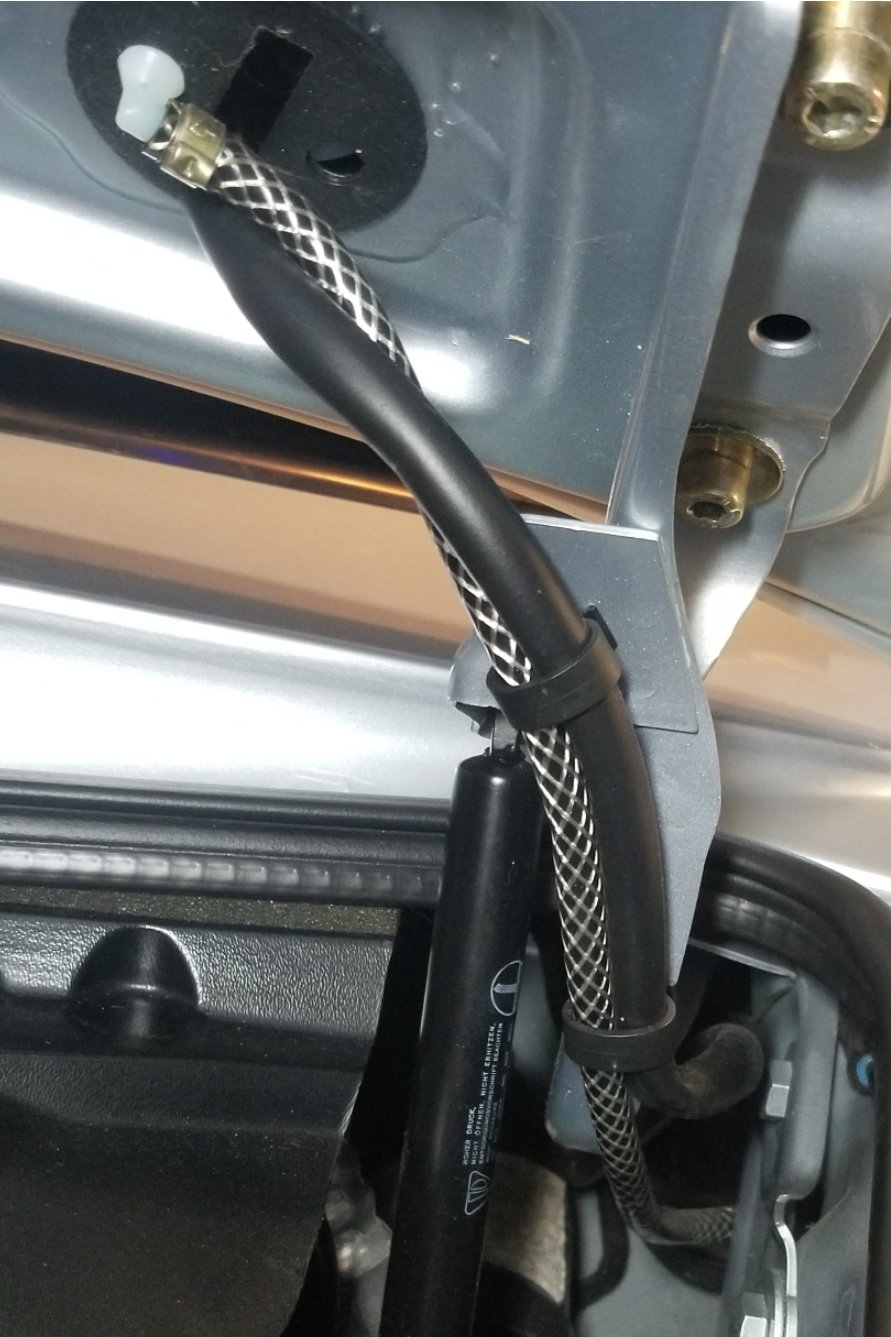


If you found this page informative return to the main page and bookmark it for future 993-related servicing, repair, and upgrading guidance & information. If it saved you some coin consider a donation through the button on the top left margin of this page.


#993 Shift Linkage #Shift Coupler #Shift Linkage #Shift Rod Coupler #Rubber Washer 
#Rubber Coupler #993 Shift Linkage #993 #Golden Rod

Wednesday, July 29, 2020

Windshield Washer Low Fluid Light Acting Wonky?


Is the dashboard low-washer-fluid light staying on even though you filled the tank all the way up to the very top? You may have a dirty or failed fluid level sensor.

The sensor is mounted to the top of the tank located inside the left front quarter panel. At first glance, it looks as though getting to it will be a big job. Turns out it is quite easy. Its mounting screws are located behind the front wheel well liner and also behind the slide-out headlamp pod. Once the screws are removed and the filler and pump connections detached it just slides right out exposing the fill sensor for removal. 

Turns out the sensor is expensive at over $100 US so I would inspect, clean, and test the old one first to see if it can be salvaged and reused before buying a replacement. 

Andy ;-)

Tuesday, July 21, 2020

993 Parts Catalogs, also Seats, Wheels and hard to find electrical Terminations/Plugs

Parts Catalog

Below are URLs to various documents that are useful in researching part numbers wheels & seats. When clicking on the URL a viewer may open a login screen. If so "X"  out of that screen to displaying the document.
To print or download these documents select the print icon that appears on the button bar at the bottom of the document image when gliding your pointer over it. The document will open in a PDF reader where it can be printed or saved to your local computer.

It is not required that you login or have an account to do this.

Rest-Of-World Parts Catalog (ROW). This catalog lists part numbers with illustrations, available in countries outside of the USA. It includes parts for vehicles and options on vehicles that were never offered in the US. Certain of these parts are not listed in the USA catalog or available through North American dealer distribution.

United States Parts Catalog (USA). This catalog includes part numbers with illustrations for vehicles sold into the USA & Canadian markets. In some cases, this is a subset of parts in the ROW catalog.

Both of the above catalogs are great for identifying part numbers, what a part looks like and how a part fits in relationship to related parts in your car.  The catalogs are dated and so do not include supersessions to later part numbers subsequent to the 993s production years. Most internet & all dealers will allow for searches under these original part numbers,  providing superseded part numbers that may have come up after the production years of the 993.

Finding part numbers for wire harness hold down and other clips in the main catalogs above:
If you look at the parts listing for the associated harness diagram in the wire harness section you will usually find various cable ties, clips, used in conjunction with each harness even though they are not called out in the harness drawing.
Some are also listed at the end of the catalog section.

Multi-Pin 
Connector
Electrical Terminal Catalog listing. In addition here you will find some of the part numbers for hard-to-find electrical plugs, sockets, and other terminations. To rotate the image for easier viewing download the file and open it in the 
free Acrobat PDF Reader and select the rotate icon. 
Terminal Pin Tool
Also if one is just replacing a bad pin or socket in a multi-wire connector there is a tool available in a couple of sizes to extract and replace individual pin connectors while preserving the overall plastic plug/socket housing.
Terminal Pins


993 Seat Parts Catalog. This is the 993 section of the seat catalog with part numbers and illustrations. To rotate the image for easier viewing download the file and open it in the free Acrobat PDF Reader and select the rotate icon.

Wheel & Tire Information. Here are some Porsche documents that are useful in researching styles and fitment of wheels for a 993 and other Porsche vehicles as well as tire size fitment. All very useful when trying to determine if a certain OE or aftermarket wheel or tire size will fit your car.


If you found this page informative return to the main page and bookmark it for future 993 related servicing, repair, and upgrading guidance & information.

Friday, July 17, 2020

Adding illumination to the Ignition Keyway on a 993


Earlier year production Porsche 993s do not have an illuminated ignition keyway.
Most of these cars have a black dash and at night it can be difficult to see the ignition keyway to insert the key. There are lots of aftermarket 12-volt bulb or  LED panel indicator lights that can be mounted above the keyway to provide illumination. Below is how to install a keyway light into one of these cars using a factory bulb holder or just an aftermarket lamp or LED. One can install an incandescent bulb as original or update the install using a pre-wired bare white or yellow 8mm or 10mm LED with the original Bulb Holder.

The picture at the top of this page is of an installed aftermarket narrow beam spotlight LED. Other styles of lamps will produce different visual effects. Be aware raw LEDS, panel lamps, and bulbs come with a selection of beam angles sometimes referred to as viewing angle or even some produce diffuse illumination. This will result in a more or less directional illumination effect. This may influence your decision as to what lamp to use and the exact placement of the light source through the dash. 


Parts needed for an original incandescent bulb install using the factory bulb holder:
  • Porsche Part number 964 632 113 01 Bulb holder Ignition
  • Porsche Part Number N 017 751 2 bulb 1.2 Watt
  • Porsche Part Number 999 632 014 00 Bulb electrical socket fits in holder Ignition
  • A short length of 18 gauge stranded primary wire
  • A few small tie-wraps & some 3M type 33 or 88 electrical tape
  • Two Scotchlok wire splices
  • Solder and soldering iron if you desire to solder the wire tap-ins

Parts needed for a LED upgrade install using the factory bulb holder:
  • Porsche Part Number 964 632 113 01 Bulb holder ignition starter lock
  • A bare 8mm or 10mm Prewired 12 Volt LED from eBay
  • A short length of 18 gauge stranded primary wire
  • A few small tie-wraps & some 3M types 33 or 88 electrical tape
  • Two Scotchlok wire splices
  • Optional - Solder and soldering iron if you plan to solder the wire tap-ins

Parts needed for installing a generic panel lamp install using aftermarket parts:
  • A small LED 12-Volt panel indicator lamp with housing and pigtail (eBay)
  • A short length of 18 gauge stranded primary wire
  • A few small tie-wraps & some 3M type 33 or 88 electrical tape
  • Two Scotchlok wire splices
  • Solder and soldering iron if you desire to solder the wire tap-ins


Where to make the electrical connections:

  • On the 993 the frunk light is illuminated along with the dome lights in the cabin.
  • The wires powering the frunk light run up the hinge arm on the driver's side of the car for LHD cars. This circuit location is where the tap-in is easily done


The procedure:
  • Cut power to the frunk light circuit:
    • Open the Frunk and use a screwdriver to press down on the lid latch to lock it triggering the switch that is part of the latch.
    • Close the cabin doors to the car and lock the car with the fob. The Frunk light should go out. 
    • The idea here is to make sure the frunk lamp is unpowered as you tap into its wires. Alternatively, you can pull its fuse or disconnect the car battery.
  • Add two or three feet of stranded automotive 18 or 20 gauge primary wire to the two connections on the bulb socket or LED pigtail depending on which you plan to install;
  • Mount the light fixture with the bulb and wires attached to the underside of the gauge cluster above the ignition keyway. To do this 
    • Remove one of the gauges to access behind the gauge cluster;
    • Punch a small hole in the vinyl dash cover where the steel behind it has a cut-out and gently position the fixture so its lamp opening or lens protrudes through the vinyl cover.
  • Then thread the wire behind the dash to the driver side frunk hinge mechanism. It may be helpful to use a fish tape to facilitate what you are doing.
Tapping in the electrical connection: 

    • Trim the excess length of the wires and splice the two wires into the two wires that run up the hood hinge arm and lead to the frunk light on the underside of the hood. 
    • To do this make a two or three-inch lengthwise slit in the upper end of the black rubber sheath running up the hinge arm containing the wires to the frunk light.
    •  The red wire leading to the lamp on my car is the positive wire, the Brown & White wire is the negative. 
    • When adding the keyway lamp wires along existing wires I like to stagger the tap-ins so their position along the existing wires doesn't overlap. This is is to avoid possible future shorts and also avoiding concentrating the insulating tape or 3M splice bulk in one spot. To accomplish this tap into the two wires an inch or two apart along the length of the wire bundle.
    • For the LED solution it is important that the positive lead from the LED goes to the positive power wire leading to the frunk light otherwise the LED will not illuminate. I like to solder splices for reliability or since the current load is very low in this application Scothlock splices can be used;
    • Insulate as needed with Scotch 33 or 88 electrical tape and tie things down as needed with small tie-wraps. Tie-down the wires so they can freely move with the hood as it is opened and closed. I strongly suggest using the 3M tapes as they will tend to not break down and unravel with age or temperature cycling as other brands of electrical tape will.
  • Pull the hood release to unlock the frunk latch before attempting to close the frunk
If you found this page informative return to the main page and bookmark it for future 993 related servicing, repair, and upgrading guidance & information.

#Alarm #fob #door lock #immoblizer #ignition kill #led flashing, #remot #entry #lighting

Sunday, July 12, 2020

Keeping things cool Oil Cooler & AC Condenser Fan

In hot weather do you hear your oil cooler or AC condenser coil fans running at the front of your car? If not you may want to look into if the fans or their low-speed fan resistors are still functioning. Most folks don't notice if their cooler fans run as they only run in hot conditions and then only very intermittently. That means for most folks, including me, there is no outward sign that they have failed. There is a concern about failed fan motors or faulty resistors raising engine temperatures or adversely influencing the function and durability of the airconditioning condenser coils. The resistors are a know failure item on a 993 and the fans and resistors are easily tested. Tore from bergvillfx.com suggests when the low-speed resistors fail the CCU controlling them default to the high-speed setting where the only symptom is a louder blower sound when running.

I have read several accounts of the original resistors used in the low-speed circuit for the Oil Cooler and the AC Condenser failing on a 993. The resistors are encased in a ceramic donut and are located in the front quarter panels, one on each side of the car. They can be tested by pulling the two relays that control the individual fans in the fuse box and jumping the two low-speed pin sockets for each relay's socket that control each fan.
The sockets to jumper are labeled on both relays, they are spade socket 30C to spade socket 87C, they are located directly across from each other in each relay socket.  (see the below wiring diagram) or their Ohm resistance value can be directly checked at their pigtail connections that for the one in the left-hand quarter panel can be accessed through the headlamp openings by removing the headlight pod. On the right-hand side, disassembly will be required to test the resistor at the pigtail end. Also if while you have the relay out you would like to test the fan motor through the high-speed setting,  jumper spade socket 30 to spade socket 87.


The jumper can be easily made by taking a short length 14 or 12 gauge solid core primary wire, for example from a piece of ordinary Romex wire, striping the end insulation and then hammering the wire flat on the ends to form a spade that fits easily into the relay spade sockets.

Using an Ohm meter on their pigtail connections they should read at about 0.45 Ohms, most meters are not very accurate as they approach zero ohms so any reading at or below an ohm is probably good to go. Also, if the resistance checks out between the wires check the Ohm value from a good body ground to one of the wires it should be an open connection (Infinite Ohms) to verify the resistor's case has not failed and the coils within have not partially or completely shorted to ground.

Tore from www.bergvillfx.com suggests that when the low-speed resistor fails the system defaults to using the high-speed setting.
The resistor on the left side can be accessed behind the wheel well liner on left-hand drive cars, the resistor on the right can only be replaced by removing the bumper cover or the cooler components behind it in the wheel well first, a big job! When they fail some folks abandon the old resistors in place relocating their replacement in the wheel well.

Here are some options to replace the resistors:
  • Do nothing if you hear the blowers running at high speed and it doesn't annoy you.
  • Buy the replacement resistors at the dealer and replace them through the wheel wells. The trick to moving the oil cooler to access its resistor is to remove the headlamp pod and a fastener behind it in addition to the fasteners in the wheel well that hold it. The OE both resistors is kind of pricy, installing new ones involves disturbing 25 Plus-year-old Oil & Refrigerant hoses whose durability may be in question.
  • Relocate replacement OE resistors and abandoning the original ones in place. Relocating them behind the wheel well liners avoiding major body or component disassembly and disturbing hoses & fitting on a 25+year-old car to replace the originals.
  • Update each of the  $75 each original 0.45 Ohm 55 Watt resistors with a pair of 100W industrial resistors of a robust design providing between 0.4 ~ 0.5 Ohm total resistance from eBay for a few dollars. Using two 0.8 Ohm 100W resistors ganged together in parallel is a lot lower cost than finding a single 0.4 Ohm resistor rated at 200W it also allows for more flexibility in where the new resistors are mounted.
  • A combination of the above option and relocating the resistors behind the headlight pods; here is a DIY project to replace and update the resistors
  • Buy a 12 Volt solid-state variable speed fan controller on eBay to eliminate the resistors entirely while retaining the two-speed fan feature. I have not done this but others have reported it works quite well. In this case, relocating the controller to the inside the frunk is probably a good idea.
  • Jumper the resistor's pigtail plug or the relay in the fuse box where the system becomes a one-speed controller that turns the fan on its high speed whenever the system triggers the low or high heat threshold. I have not tested this option and it is unclear if it will damage the CCU or has the potential to throw an OBD code. If Tore is correct and the system defaults to high speed when a resistor is bad anyway and so it may simply be unnecessary. The wiring diagram seems to have a feedback wire in the system whose function is unclear to me so I assume it is part of the CCU system related to On-Board Diagnostic Code (OBDC) reporting.
Here is the wiring diagram for the fan control circuit for those who entertain replacing the resistors or jumpering their connections:


Sunday, July 5, 2020

How to remove and reinstall the front seats without drama and add a little leg room too!


For some reason, Porsche decided to use special socket-head DIN6912 M8X20 screws with shallow Allen heads to mount their seats. This has caused seat removal to get to the DME, alarm controller, or audio amp a tortured experience for some. The issue is when unfastening the seat the cap screws' head socket strips during removal. Below is how to remove a seat with a minimum of this drama:

Removing the seat:
6mm Allen wrench
  • First, put a drop of odorless penetrating or sewing machine oil on each of the seats mounting Allen head cap screws and give it a few days to soak in.
  • Do not use PB Blaster or some other acidified penetrating oil as it will take years to get the acrid smell of the oil out of your car! Don't ask me how I know this.
  • Raise the seat both front and back to its highest position
  • Remove the capscrews that hold the seat down. 

    • Be sure to use the right size Allen wrench and care to fully insert the wrench holding it square to the capscrews' heads to not strip the screws socket when releasing them. Using an Allen wrench of high quality may avoid stripping the head.
    • The force applied to remove feels relatively high and if not previously removed the capscrews release with a "pop" sound.
    • Use high-quality preferably new Allen wrenches as the cap screw heads are easily distorted and stripped. Some use a special 6mm  DIN6911 hex key bit with a center piloting provision pictured below however, I have never used such a tool.
    • It may be advisable to have a few replacement capscrews on hand from the dealer to replace the ones that become gnarled up during removal. The issue is with even slightly gnarled ones they may be problematic and strip the next time one plans to remove the seats.
  • Unplug the seat's power seat and seatbelt warning light pigtails and lift the seat out of the vehicle. The seat is heavy and best removed with the back folded forward taping some cardboard down to protect the door threshold from scratches if you bump it.

Important reinstallation notes:


  • The four rear of the track capscrews per seat has two washers under them. this looks to be so the unthreaded section of the capscrew's shank does not come into contact with the threaded holes in the backing plate. Doing so would strip the backing plate threads weakening the seat mounting.
  • According to the catalog, the front labeled #11 above and the rear washers labeled #5 above are different in thickness and possibly hardness so make sure you reinstall them in the same positions.
  • All washers have a top and bottom the tops have smooth edges the bottoms have sharp ones. When reinstalling the mounting capscrews be sure to face the smooth side of the washers face up under the capscrews' heads to avoid damaging the small fillet under the head significantly weakening the capscrew and therefore compromising the safety of the seats' mounting.
  • A torque value of 23nm or 17 ft-lb should be used for the mounting capscrews that are lightly oiled. Tighten the rear capscrews first and then move the seats back and tighten the front.
  • Verify the seat/rail position

Getting a little extra legroom  when remounting the seat:
  • If your seat was originally mounted in the forwardmost mounting holes on the seat rail pedestals one can move the rail back to the second set of holes on the pedestal's frame. In the rear of the rail, the rear threaded pedestal backing plates can be slid rearward to line up with the two further back mounting holes. The front holes in the pedestals are both threaded to receive the mounting capscrew. Moving the rails back will give you about an inch more legroom and a little greater clearance between the seat and the steering wheel to get in and out of the car. 
  • Beyond this seat rail extensions, marked in red in the picture below, are available that are placed on top of the seat pedestals, pictured in yellow. They allow for attaching the seat even further back by
    Under Seat View 
    about an additional inch and add a small amount of height. They can be purchased from:
R.P. Mack Motorsports. 
Phone: (616) 844-4162. 


If you found this page informative return to the main page and bookmark it for future 993-related servicing, repair, and upgrading guidance & information. If it saved you some time, aggravation or even some coin consider a donation through the button on the top left margin of this page.

Search terms:
seat removal strip stripped screws Allen DIN6912 M8X20
#seat #removal #strip #striped #screws #Allen #DIN6912 #M8X20

Wednesday, July 1, 2020

Battery Maintenance even for so called Maintenance-Free Batteries


Hot weather, long stays on the battery tender or just normal use in the car all contribute to electrolyte loss in one's car battery.

Time to check the level and top it off.
Even if you have one of those maintenance-free Interstate batteries privately branded Autozone or other the one-piece cover that functions as a lid for the six cells underneath can be gently pried off and the cells topped off with distilled water adding years to its service life. 

The top-off level is to add just enough fluid when you see the liquid touch and cling to the round fill ring at the bottom of the neck of each cell access hole. If you see the cell plates above the water level when you first look into one of the cells you are just in time to save your battery as they should be submerged at all times. At one time batteries had individual screw-on or snap-on covers for each cell or two covers each covering three of six cells this is no longer the case with so-called maintenance-free batteries. 
Battery Cover

On many maintenance-free batteries, the cover is a single plastic band that runs across the entire width (longer dimension) of the battery in the middle of the battery top covering all six cells.  This is how my most recent Interstate branded battery is. On the Interstate battery, the cover can be obscured by an adhesive label but can still be pried off using a screwdriver or a one-inch metal paint spatula gently prying it up while moving along the seam of one of the longer sides of the cover. Once the cells are filled reseating the cover involves laying 2x4x15" or some other block of wood over the entire width of the cell cover and gently tapping it in, flush to its original position.

Unfortunately, some designs of maintenance-free batteries don't allow one to get to the cells to fill them, or at least I haven't figured out how to do it. Now, I just stick with the 993/964 compatible style Interstate brand or store brand battery manufactured by Interstate with the long cover strip down the middle that doesn't have this issue. 

Don't forget to reattach the fish tank hose battery breather tube when you are done. On my Interstate Battery, there seem to be two breathers one at each end of the battery so I purchase a plastic tube vacuum line tee and added some additional fish tank hose so both are vented through a hose. Others have plugged one of the vent holes connecting a single vent tube to the remaining breather. I don't smell any acrid odors in the frunk by using the vent tubes and that works for me!

Hope this helps, 
Andy 
                                          
If you found this page informative return to the main page and bookmark it for future 993 related servicing, repair, and upgrading guidance & information. If it saved you some time, aggravation or even some coin consider a donation through the button on the top left margin of this page.