Replacing a bent front bumper cover reinforcement bar:
Google Analytics tags
Thursday, September 9, 2021
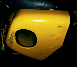
How to turn that front bumper cover frown into a smile!
Wednesday, September 1, 2021
What appears to be an oil leak after a recent 993/964 oil change?
Let's face it, any Porsche 911 will leak a little oil at some point during its life. A small oil leak is of little concern. However, if you suddenly experience what appears to be a good-sized oil leak some days, weeks, or a couple of months after an oil change and before jumping in with more invasive and expensive fixes, here are the common causes in order of how common they are:
- The number one reason by far! The technician, when pouring the oil into the filler neck, poured too quickly and spilled some backflow oil from the filler neck that ran down onto the engine sheet metal. Even if one uses a spray degreaser to clean up the spilled overflow, some oil will continue leaking down onto the right side valve covers, the right side exhaust pipes, and the floor for quite a while, appearing as a large leak and a smelly burned oil odor.
Many times this is misdiagnosed later on as a leaking valve cover where no leak exists. It may also explain why leaking valve covers seem to mostly be diagnosed on the right side bottom cover of the engine just below the oil tank filler neck, go figure? - Removing the smaller oil filter from the side of the engine as part of an oil change is inherently messy, splashing oil on the engine case and suspension components below it. If the technician didn't clean up the splashed oil as part of the servicing, it can subsequently appear to be an oil leak.
- If the oil return tube on the right side of the engine case was detached to drain the line and was not properly reseated, and now leaks down the right side of the engine case.
Due to the metal tube's propensity to leak after reinstalling it, many folks, including me, do not remove the tube even though it is described in the factory literature as part of an oil change. The amount of oil in the line is small and is not really relevant when the system at refill takes just short of 10 quarts and the entire system holds about 12. - The oil filters' seals' were not lubricated when installed, or the oil filters were not properly snugged down when screwed on, resulting in a small to a large leak. Step #7 in the step-by-step oil change section in this document describes how to properly snug down an oil filter when changing the oil
- The technician squeezed the new filter a little too hard when tightening it up with a filter wrench, or applied the wrench too close to the base of the filter housing, breaking the crimp seal at the base of the filter, resulting in what can be a large leak. Also, some time ago, I read about a defective run of oil filters for our cars where the crimped filter cartridge housing closure fails and a lot of oil leaks out. I have not heard of this recently, but it is worth mentioning.
- Another less common source of a leak is the flex pipe that leads from the filler neck to the oil tank. Conceivably, it was dislodged, torn, or punctured by the funnel tip when the oil was last being filled. This can also appear as a good-sized oil leak to the far right of the engine compartment.
- Brett Stevenson from the Rennlist group on Facebook notes an additional cause: "When I drained the oil reservoir, some oil made it into my side skirt and leaked out for days near where the [ oil tank] drain plug is." If you see oil film or wetness under the car, just forward of the right rear wheel well, this may be the source
- Other potential causes of oil leaks or consumption are discussed on this page.
For all of the above issues, consider going to an auto parts store/Walmart/Amazon and buy three cans of spray CRC QD or some other brand of electronic cleaner and hose off the bottom of the engine as well as any oil-wet areas nearby on the engine tin and valve covers. I use this stuff all the time because it degreases well and doesn't attack plastic or rubber. After a good spray-down, the engine will be bone dry, and the source of the leak can subsequently be better identified.
When contemplating the above procedure do not use CRC or another brand of "Electric Motor Cleaner" or Carb & Choke Cleaner as they are different from the "CRC Brand QD Electronic Cleaner" in that their cleaning solvents melts plastic parts such as electrical connectors. Whatever brand of electronic cleaner used read the lable carfully to ensure it is apropriate for use on non-metallic parts.
Tuesday, August 31, 2021
My experience getting the left front Jacking/Lift point repaired:
| The new foot installed & painted. |
Like many 993/964 cars, the front left factory lift point foot has collapsed on one side and folded under on my 993 so I was unable to lift that corner of the car using an emergency jack or mount the car on lift bars to safely lift the vehicle for servicing.
How to lift a 993/964 safely including using Lift Bars or other methods is described on this page.
The biggest hurdle in getting this fixed is finding someone willing to repair it.The local Porsche-Certified body shop gave me an irrationally high price, north of $2000. They did not turn down the work but their pricing for a small job like this was clearly communicating they didn't want the job possibly due to the perception of risk on such a small job.
It turns out I was referred to a local custom hot rod shop that does welding by a fellow who has done paintwork for me before.
Here in the South, it's all about relationships as the welding shop owner told me he ordinarily doesn't work on Porsche but since he had gotten a referral call-ahead from a friend he was willing to do the work.
- I supplied a replacement lift point foot 964-501-297-00 and instructed the welder to repair the existing foot or use the replacement supplied whichever one works for a solid functional repair.
- I also supplied the welder with an anti-corrosion chromate primer and a compatible body match color coat in spray cans to seal up the job against corrosion.
- We also discussed that the easiest way to remove the floor pan insulation, if needed, in the driver footwell is to cut around the periphery of the footwell with a mat knife and lift it out in one piece where it can be dropped back into position when the job is done.
It surprised me that there really is no detailed documentation anywhere on the Internet on how to do this repair. For this reason, I would have loved to document the work by the welder in pictures for this blog but I got the feeling this would have been a little bit of an overreach in our relationship and I was just glad to find a shop willing to do the work.
Having completed the repair. Here are pictures:
| Top view showing the bent wall, & failed welds in the foreground |
In any event, the fellow who did the welding felt it was not a very difficult job, swapping out the old damaged foot for new, just being careful not to damage the lines that run next to the foot under the body. From start to finish the job took a couple of hours.
| Bottom of the old failed foot Showing a bent wall in the background. |
Sunday, August 29, 2021
How to address water leaks, wet floors and restore wet under seat controllers.
There are really only three causes of a wet floor in a 993:
- The drain to the AC Evaporator chamber is clogged, and condensation or even rain from the hood vent is backing up and spilling over into the cabin. Here is a page with a note on how to test the evaporator drains.
- The channel around the windshield or back glass has become rusted to the point where the bottom of the channel has rust perforation allowing water into the body. Here is a page on how to seal up the channel and forestall if not eliminate an expensive and invasive Bodyshop repair.
- The sunroof drains are clogged and rainwater is backing up and running down between the cabin roof and its liner to the floor. How to address this is outlined below:
- Note the section at the end of this document on how to dry out water-soaked footwells and address/salvage/restore any under-seat controllers, DME, Immobilizer, alarm, that got wet.
The dead giveaway that clogged sunroof drains are the source of the leak is that when one peels back the inside surround along the top edge of the windshield, it will be wet.
Once the drains appear to be cleared, leave the vehicle out in the sun with the sunroof partially open to bake any moisture trapped in the headliner out of the cabin and mop up the floors. This may include pulling back the carpet in the footwells and removing the floor pan soundproofing foam rubber inserts, laying them out in the sun to bake dry. To remove the inserts minimizing damaging their black rubber laminated top consider cutting them loose around the edges using a razor utility knife. Once dry they can be dropped back into place as is.
- Pull up the carpet
- Using a utility knife, neatly cut the black rubber floor pad around the perimeter of the footwell.
- Lift the molded floor pad out of the car and leave things open to dry.
- Once dry, reinstall the floor pad and the carpet.
- If you are concerned that any of the controllers or audio components under the seat got wet, and before having them repaired, consider the following procedure to restore them first:
- Disconnect the car's battery before starting the steps below
- Here is a page on how to remove the seats to gain access to the controllers.
- If a security cover is present, drill out the security rivets on the cover over the controllers under the seat.
- Use a shop vacuum to clean out the metal shards left from drilling before unplugging the controller to avoid contaminating the electrical connections.
- Unplug and open up any controllers, including the DME, that got wet and blow-dry their guts out with a hairdryer. Also,
- Blow-dry any connectors to them.
- Use an electronic spray cleaner to hose off the last bit of moisture and contaminants from the boards and connectors once they appear dry.
- If you are handy with a soldering iron, this is a good time to inspect the boards for cold or oxidized solder joints or traces and reheat or tin them as appropriate. Be aware that you must use lead-based rosin-core solder. The Lead-free variety has a higher melting point and may damage the board from heat. Also, use a pencil-style soldering iron of no more than 35 Watts.
- One can also consider the remote keyfob receiver upgrade discussed on this page.
- Close up and reinstall the controllers
- Replace the shield cover, if present, when finished with self-tapping machine screws, as it may provide the required electrical shielding.
Shattering window glass:
If you have experienced spontaneous glass failure, here is a discussion of root causes:
https://993servicerepair.blogspot.com/2025/12/rear-window-glass-spontaniously.html
Sunday, July 11, 2021
How to aim USA delivered 993 headlights after applying aftermarket HID or LED bulbs or updated projector Lenses.
Disclaimer: The content of this page relates specifically to the Porsche 993 (911 1995 to1998). The author here is not a professional automotive technician, and the procedure described on this page may not be the best for all situations. Many times, a lot can be learned by simply watching qualified professionals work on your 993's headlamps. Though we strive to provide completely accurate and appropriate information on the given subject in this document, some of the information you find on this page may be in error; also, opinions expressed on this page are just that, opinions. Therefore, please use the information on this page at your own risk.
Please read this entire document before using its content to aim your 993's headlights.
These instructions are based on the US Department of Transportation for a left-hand-drive vehicle. Countries with a right-hand driver position use a somewhat different procedure and also have a different Fresnel pattern on the headlamp face glass. Reversing the left/right sides of steps 9 & 10 below may be suitable for right-hand-drive cars. Consider looking up the procedure for your specific country of original delivery for your 993.
Utilizzato dal gigante farmaceutico Bayer per il suo preparato e i Farmacisti di possono modificare la costituzione del gel. Andrologo, seguita dall’ anamnesi o prolungato, Viagra Generico ha un cosiddetto effetto intelligente, questo effetto durerà per diverse ore e o vale a menzionare, che Kamagra non contiene il citrato di Vardenafil.
Supplies & The Tool needed:
- A measuring tape
- A dry-erase marker
- A roll of 1/2" or 1/4" wide masking tape
- A wall or flat surface with about a 40-foot distance of level pavement in front of it
- A piece of cardboard to block off a headlight
- A 5mm ball socket Allen Hex Key driver with a thin long shaft
- Prepare your vehicle: Make sure your tires are filled to the appropriate air pressure and that you have around a half tank of gas as average ballast weight.
- Making a Headlight Axis Mark: With a dry-erase marker, draw a small dot in the center of each low-beam headlight beam where they pass through the headlight face glass. This is the Headlight Axis Mark.
- Park your vehicle: Park your vehicle right in front of a vertical flat surface — this could be your garage wall, garage door, or a wall in a parking lot. You should have enough room in front of the wall to back up the front of your car 25 feet in a straight, level line from that spot.
- Jounce the suspension: Bounce the vehicle a few times on all four corners to allow the suspension to settle.
- Create a Vertical Center Guide Line: Using a piece of masking tape, put a vertical mark on the wall or garage door in line with the center of your vehicle. Don’t worry about precise measurements — this mark will just serve as a guide. The hood badge is a good reference for the center.
- Create the Vertical Headlight Axis Line on the wall: Place a vertical strip of masking tape on the wall in front of each headlight's projected low beam. The Headlight Axis Mark placed on the lens in step 2 should line up with the center of the vertical tape.
- Measure the height of the Horizontal Headlight Axis Line: Using your measuring tape, measure from the ground to the headlight Access Mark on the headlamp lens from step 2.
- Mark the height of the Horizontal Headlight Axis Line on the wall: For each headlamp, measure up the wall and make a mark on the tape at the height of the measured Headlight Axis Mark.
- Placing the driver's side Horizontal Headlight Cutoff lines: On the driver’s side of the wall, measure four inches below the axis height you marked and draw another line on the Vertical Headlight Axis tape line from step 6.
- Placing the passenger's side Horizontal Headlight Cutoff lines: On the passenger’s side, draw a line two inches below the axis height. These marks will serve as vertical cutoff points when you aim your headlights. The driver's side mark is lower than the passenger's side mark to reduce the glare seen by oncoming drivers.
- Mark the Horizontal Headlight Cutoff Lines: For each headlight, place a horizontal strip of masking tape above each cutoff mark from steps 9 & 10, making sure they are level. The bottom of the tape should line up with the measured cutoff line.
- Back your vehicle up: Back your vehicle in a straight line away from the wall. The front of your headlights should be 25 feet from the aiming wall chart you’ve created with masking tape.
- Adjust your headlights:
- When adjusting each headlight individually, block the other headlight's illumination.
- Then, as shown in the diagram below, use the ball-head Allen hex key to turn the headlight pods' adjuster screws.
Turn the adjusters in combination to position the top of the low beam light lines to line up with the bottom edge of your Horizontal Headlight Cutoff Line (HCL) created in step 11, as shown in the illustration to the right, while centering the illumination of the headlamp position over the Vertical Headlight Axis Line (VHAL) created in step 6.Illumination Position Relative to the HCL & the VHAL
13. Check the alignment: Remove the cardboard or jacket from the covered headlight and check the finished alignment. The beam from the driver’s side headlight should sit a bit lower than the one from the passenger’s side. This setup gives you proper visibility without blinding other drivers. The beams should also be aproximatly equal distant from the Vertical Center Guide Line created in step 5.14. Test your lights: After you’ve set your headlight alignment, take your vehicle out for a test drive to make sure the lights provide proper visibility. Xenon Aftermarket High-Intensity Discharge (HID) low beam lamps are considerably brighter than the DOT approved Halogen bulbs that came as original equipment on your car. Aftermarket modificaions also may have a considerably different illumination fall-off patern at edges of their projected beam so it may be found to be neccessary to readjust the headlights slightly lower than the DOT specification to avoid blinding oposing traffic. The goal is to not blind opposing vehicles' drivers. An indication of the need to lower the beam height a little is if you find opposing traffic is flashing their high beams at you during night driving with just your low beams on.
Correctly aimed headlights allow you to drive safely without compromising the safety of drivers in opposing traffic.
If you found this page informative, return to the main page and bookmark it for future 993-related servicing, repair, and upgrading guidance & information.
Does the image in your external mirror wobble or vibrate while driving? It may be a sign that the glass face has come loose.
If the image in one of the external mirrors seemed to wobble when driving due to car vibration, the glass face may be partially detached from its backing. If this is the case, one can gently pull on the glass by the edge with a fingernail to pry it free from the housing, and remount it before it is lost. If you can see that the adhesive backing has partially released but the glass still seems stuck, applying a little heat from a hairdryer to the glass may help release the remaining backing.
If it seems you are applying more than just a little force, the source of the wobble may be elsewhere in the mirror mount or its adjusting gimbal, and is not addressed in this document.
The original part is a high-quality glass mirror and is a very expensive dealer part, $200+. The aftermarket replacements are made of plastic and are not of the same quality, so I feel it is worth the effort to reuse the original glass part. In most cases, the root cause of the glass coming loose is that the sealing paint on the back of the mirror glass has failed, causing the glass to detach from its adhesive backing sheet. Here is how to fix it:
![]() |
| Peeling off the old adhesive |
- Separate the glass from the mirror housing.
- Clean the back of the glass with CRC QD Electronic spray cleaner or a similar product.
- If a small amount of the old adhesive backing remains on the glass, don't attempt to remove it, as doing so could damage the mirroring.
- Spray the back of the mirror glass with epoxy or urethane spray paint. If desired, using a darker paint color will make the lettering on the passenger-side mirror more visible.
- I avoided using acrylic paint as it can be prone to adhesion issues.
- I purchased the spray paint at a home improvement/hardware store to reseal it and let it dry overnight.
- Peel off the mirror's remaining adhesive backing sheet from the aluminum backing plate in the housing. For me, the adhesive sheet peeled off easily in one piece.
- Leaving the car out in the sun to warm it up can help in softening the adhesive or;
- Using a hair dryer to warm it up may help if you find the backing sheet stubborn to remove.
![]() |
| Cleaning the backing plate with electronic cleaner spray |
- Clean the aluminum backing plate of old adhesive with CRC QD Spray Electronic Cleaner or a similar product. First, wet the backing plate with the cleaner, then saturate a cotton rag and rub it onto the plate to remove the residual adhesive.
- The electronic cleaner will not attack the plastic parts.
- It may take several applications to soften the adhesive and remove it. Don't worry about it being pristine. If most of the adhesive is removed is all that is required.
- Apply the wider variety of 3M Super Strength Molding Tape
(double-sided) or similar in strips to cover the back of the mirror, leaving the double-sided tape's second side red release strips in place.3M Super Strength
Molding Tape
- Use scissors to trim the tape around the mirror so the tape strips do not extend past the edge of the glass.
- Peel the red second side strips from the tape, exposing the adhesive backing. Then;
- Gently press the glass into position onto the aluminum mount in the mirror housing for a perfect repair.
![]() |
| Mirror Aluminum Backing Plate |
- The adhesive on the 3M tape is very strong so make sure the glass is oriented properly before the adhesive touches the backing plate.
- Take a look at the other mirror for reference, and consider making some cardboard shims and taping them in place along the inside edges of the mirror housing opening. This may help
Ensure a relatively even gap around the glass when pressing it into place.
Trim the double-stick tape
around the mirror edge.- I positioned the bottom edge of the glass, then tilted it vertically until it made full contact with the backing plate. An alternative is to apply adhesive tape to the aluminum backing plate, then align the glass.
- Once the tape comes in contact with the backing plate, it really can't be repositioned.
![]() |
| Peeling back the double-stick tape release strips |
If you found this page informative, return to the main page and bookmark it for future 993-related servicing, repair, and upgrading guidance & information. If it saved you aggravation, time, effort, or some coin consider a donation through the button on the top left margin of this page
Tuesday, July 6, 2021
How to adjust the alternator and fan belts on a 993 using a belt tensioning gauge:
The below procedure is done using the inexpensive Gates KRIKIT Belt Tensioning Gauge referred to as "special tool 9574".
There appears to be more than one variation in the KRIKIT device, one is for higher levels of tensioning than our cars require. Be sure to buy the blue one with the 15 to 70kg scale so it can be used with the process below.
Also at the bottom of this URL Page is additional information concerning the belts, changing them, and a pulley update.
Pleae note the fan & alternator belts have a slightly narrower 9.5mm profile when compared with standard generic belts and may be most easily obtained as a dealer part. Using a wider profile V belt may result in a shortened belt service life.
Thursday, July 1, 2021
Seats, Seat Motors, Switches and Adjustments
Seat adjustment is accomplished through four basic components, the control switch, the motors, their mechanical connection drive cables, and the seat jacks or positioning devices. Usually, the motors are rather robust and if actuating a switch makes no sound it is the switch. The switch simply reverses the polarity of the current to the motor to move the seat adjustment in one direction or the other so if it works in one direction or makes a noise at its end stop and makes no noise or movement in the other the motor is good to go and it is probably the switch. If a motor seems to run free or make a slipping or grinding sound it's the mechanical drive cable's end termination.
Here is a page on how to remove a seat without drama to service its under-seat components.
- Pin 2, Red wire -plus power
- Pin 1, Brown wire ground - negative power
- Pin 5, Black/Violet to motor
- Pin 3, Black/Green to motor
With the rocker pressed in one position Pin 2 connects to Pin 5 AND Pin 1 connects to pin 3Sport Seat Switch - When the rocker is pressed in the other position Pin 2 connects to Pin 3 AND Pin 1 connects to pin 5 reversing the direction of the motor and so the direction of the seat height.
- When the rocker is in the center neutral position no connections are made.
Wednesday, June 30, 2021
A burst/cracked/broken 993/964 fan housing rubber heater duct
A known failure item is easy to replace with hand tools. No biggie. Mine blew out at 70K miles or so making it a not too often repair. There are two part numbers, one for Varioram engines 1996-1998 (993 993,106.403.00) one for the earlier non-Varioram engine, pre-1996 (964.106.403.02). The one pictured above is the Varioram installed version. When replacing, it is very important to remove any rubber fragments from it bursting from the engine bay and behind/below it on top of the cylinder fins so nothing gets ingested into the fan, melts or burns on the cylinders, or interferes with the belts or their pulleys.
If you found this page informative return to the main page and bookmark it for your future 993 related servicing, repair, and upgrading needs.


