Google Analytics tags

Thursday, October 14, 2021

Is your parking / emergency brake lever getting harder to pull ? A quick and easy fix!


On a 993 or really any 964 or earlier 911 the parking lever is used every time the car is parked. As the parking brake shoes wear incrementally over many years the lever must be raised incrementally higher in its travel to lock the parking brakes. As the lever requires a longer pull it becomes ergonomically harder to pull it and the mechanical leverage it applies to the parking brake seems to diminish. I never noticed this change as it happens very slowly over many years. However, my wife was going to drive the Porsche and complained she didn't have the strength to release the parking brake once I had pulled it up. 

Turns out adjusting the parking brake lever is very easy:

First, one removes the back top section of the between-the-seat console. If your car has the plain cup, labeled "10" in the illustration below, just remove the rubber pad in the bottom of the cup and unscrew the two Phillips screws to release it. It takes a little jiggling of the cup back and forth to allow it to come free. If your car has one of the optional Tape or CD holders the screws are still there but it will take a little investigation to see how to release the holders to get to them as I do not have either of these in my car.


Once the cup is removed it exposes the cable saddle, labeled "24" in the above illustration, attached to the brake lever and the two cables leading the rear brakes. There are two nuts one to adjust the take-up slack on the cables to the wheel ends, the other being a jam-nut against it to hold it from slipping. 
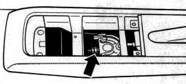
Jam & Adjusting nut location.

Release the adjusting nut from the jam-nut using two open-end box wrenches. As you tighten up the adjustment nut trial pull on the brake lever. In my case, I tightened it up to the point where when the lever's ratchet clicked 4 times before I began to feel some resistance from the brake cables through the lever. The key here is to NOT tighten the nut too much so the parking brake is always partially engaged as this will create heat in the rear wheel hubs and wear the brake shoe linings, both very undesirable conditions.

Once adjusted re-snug the jam-nut against the adjusting nut and button things up. It took me all of five minutes to do this adjustment & as they say happy wife happy life!

Adjusting the Emergency/Parking  Bake after replacing the brake shoes:

The brake shoes are extremely long-wearing. I checked mine on my previous '86 Carrera at 150K miles and found they still had plenty of lining. However if one is going to replace the parking brake shoes, or simply wants to readjust the shoe clearance at the wheel ends when the wheels are off for other reasons here is the factory document on how to adjust them::


If you found this page informative return to the main page and bookmark it for future 993 related servicing, repair, and upgrading guidance & information. If it saved you some time, aggravation or even some coin consider a donation through the button on the top left margin of this page.


#handbrake

#parkingbrake

#brake
#brakes

Wednesday, October 13, 2021

AC blowers appear to be on the firtz - Cleaning the sliders/fan switch/temp control and replacing the faceplate backlights


Recently the AC in my 993 started to act strangely. With the AC-Max button pressed the blowers would work intermittently and I found that wiggling  the sliders on the Climate Control Unit (CCU) caused the blowers to work.

I diagnosed the issue as dirty slider potentiometers and dried slider grease. Below is what I did to remedy the situation:

The procedure below can also be used to access the CCU display backlight bulbs for replacement or upgrade.

Removing The Climate Control Unit (CCU):

1.       Disconnect the negative car battery lead and tie it out of the way so it can’t fall back onto the negative battery post.
2.       Cut some thick coat hanger wire into 4 straight sections of about four or five inches long and clean the cut ends of any bures from cutting them.
3.       Insert the 4 coat hanger wires into the holes on the 4 corners of the Climate Control Unit (CCU) to unlatch it from the dash.
4.       Push the CCU from behind to start its removal from the dash and then gently pull it out from the front to gain access to its wiring harness connectors.
5.       Do not pry the CCU out by its face plate edges, this can damage the faceplate.
6.       Release the two harness connectors on the back of the CCU by pressing in on the release levers on one of the narrow sides of each connector.
7.       If the lever fails to make the latch release completely, you may need to help release each connector latch from the side with a jeweler screwdriver.
8.       Once the latch on one end of the connector is released the connector is detached by pivoting the entire connector off the opposite side of its socket.

The back of CCU shows the two wiring harness connectors and the sensor blower. Note that the smaller harness connector pivots off from the outside edge of the CCU housing for removal while the larger connector pivots off from the other side.


9.       Remove the CCU from the front of the dash, this may require gently moving the steering column levers around so the CCU has a clear path of removal.

Once the CCU is removed:

1.       Detach the small sensor blower from the back of the unit by releasing the two hex nuts and washers attaching its frame to the CCU housing and unplugging its electric plug.
Sensor Blower

2.       Very gently remove the faceplate slider caps and the rotary knob caps from the CCU and set them aside.
3.       Press in on the six plastic retainer latches three on the top and three on the bottom of the CCU case and gently pull the faceplate loose from the CCU housing.

Shown are three of the six latches that retain the faceplate to the CCU body. 


4.       Release the electrical connector latch that holds the internal CCU wiring harness connector to the back of the faceplate and unplug the connector.
5.       The faceplate with the switches attached should now be loose in your hands.
6.       Remove the hex nuts and washers from the shafts under the rotary knobs previously removed.
7.       Releasing the circuit board from the back of the CCU faceplate by gently pressing on the plastic latches that retain the circuit board.

The circuit board is mounted on the back of the faceplate. The black part on the far right is the thermal sensor mount. The rotary potentiometers are to the right and left of the black slider potentiometers.


8.       When lifting off the circuit board from the back of the faceplate simultaneously, gently slide the thermal sensor with its mounting from the back as well. It is attached with delicate wires.
9.      Saturate the slide switches from the front of the circuit board on which they are mounted with an electronic spray cleaner such as CRC QD Spray Electronic Cleaner using the spray can’s extension tube.
10.   DO NOT USE SPRAY ELECTRIC MOTOR CLEANER, it will melt the plastic components.
11.   While the slide controls are wet with the solvent move the sliders back and forth to release contaminants from the slider potentiometers. Aim the solvent into the slide slots to do this.
12.   Do this procedure twice to ensure all the grease, contaminants, and oxidation are cleaned out of the sliders.
13.   Spray saturate the rotary knob potentiometers by aiming the extension tube on the can into the openings on the sides of the potentiometers on the front of the circuit board.
14.   While still wet with the solvent rotate the potentiometer knob shafts back and forth to clean the contacts inside the rotary potentiometers.
15. Spray saturate the switches from the back of the faceplate and actuate them to clean their internal contacts and plug pins and saturate their matching sockets on the curcuit board to clean them as well in case the AC related switches are a contributing factor to the blowers cutting out.
Steps 13, 14 &15 above were added after a discussion with Tore, from Bergville FX, an acknowledged expert on how the CCU functions where he suggested alternative root causes for the blowers cutting out.
16.   Use a hairdryer set to warm to evaporate any remaining solvent and moisture condensation that has formed on the circuit board and its component from the solvent cooling the components.
16.   Use a tiny drop of dielectric grease on the end of a jeweler's screwdriver or toothpick and grease the metal track inside the slot on the slider potentiometers.
18.   Also, use a tiny drop to lube the contact points of the clear plastic levers where they slide along the potentiometers’ outside housings.
19.   Move the sliders back and forth to distribute the grease.
20.   The goal is to use just enough to cause the sliders to move smoothly without binding. Using too much will migrate onto the contacts in the potentiometer causing functional issues.
21.   Wipe off any excess dielectric grease from the potentiometer’s housing

Buttoning things up:

1.       If desired inspect, test or replace the CCU display backlights by removing the bulbs via their mounting bayonets on the back of the circuit board.
2.       Press the circuit board back onto the clips on the back of the CCU Faceplate making sure its connection pins to the faceplate switches properly engage and the circuit board is fully seated.
3.       Slide the thermal sensor mount over its vent mount on the back of the faceplate
4.       Put the washers and nuts in position over the rotary knobs on the front of the faceplate
5.       Very gently snug down the rotary potentiometer hold-down nuts.
6.       Reinstall the rotary and slider knobs, both only go on one way, use care to observe how the knobs fit over their matching posts. Trying to force-fit them when they are not positioned correctly will damage the potentiometers.
7.       Reattach the internal wiring harness from the CCU case to the back of the faceplate
8.       Orient the internal thermal sensor vent duct tube to the back of the faceplate so the back end of it is correctly oriented to slip over the rectangular sensor blower opening correctly.
9.   Gently snap in and fully seat the faceplate to the CCU housing while ensuring the thermal sensor's vent duct slips over its mounting on the back of the faceplate.
10.   Blow out the CCU sensor blower of accumulated lint. If clean and not worn out, the blower blades should spin freely and silently, then reattach it and plug it back in. If the blower can't be made to spin smoothly and freely once cleaned it can be replaced. Here is a page with a section on how to replace the blower economically. Also Tore offeres an aftermarket blower upgrade that eliminates blower issues from lint accumulation going forward.
11.   Reattach the CCU connectors to the car’s wiring harness plugs in the dash making sure the connectors are fully seated.
12.   Slide the CCU back into the dash.
13.   Reconnect the car battery, fire the car up, and try the AC.

The process above took about an hour and gets a solid 2 on a 1 to 5 difficulty scale.

Related topics: